No products
Categories


Online only
ICOM - IC-7610 - HF/50MHZ, 100 W, 99 canaux, tous modes
IC-7610
New product


New Version #33 - European Market 2026
By buying this product you can collect up to 36 loyalty points. Your cart will total 36 loyalty points that can be converted into a voucher of 36,00 €.
 Pay it by wire
and save an additional 25,86 €
More info
RF Direct Sampling Takes You to the Next Level
with Advanced RMDR and True Dual Receive
Whether it is poor band conditions, or battling to pick out a call in a large pile-up, faint signals have always been a challenge for DXers and Contesters around the world. The difference between putting the QSO in the log or having to try another time is the capability of your receiver. One key factor is the RMDR capabilities, the ability to pick out a faint signal in the presence of stronger, adjacent signals. The IC-7610 introduces dual RF direct sampling receivers, achieving 110dB RMDR, rivaling that of top-of-the-line transceivers.
Innovative RF Direct Sampling System
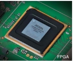
FPGA Introduced with the IC-7300, Icom’s RF Direct Sampling System has made SDR performance affordable. Direct Sampling means incoming RF signals are digitized by the Analog-to-Digital Converter and immediately processed by the FPGA (Field-Programmable Gate Array). This process greatly reduces distortion that naturally occurs in the various mixer stages found in traditional superhetrodyne receivers.
Astonishing 110 dB* RMDR
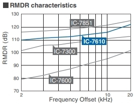
RMDR characteristics The RF Direct Sampling System in the IC-7610 is capable of 110 dB RMDR. This performance gives you the ability to pull weak signals out of the noise of strong adjacent signals. There is a difference you can actually hear as the desired signal comes out of the pileup!
* Representative value at 2 kHz frequency separation (Received frequency: 14.2 MHz, Mode: CW, IF BW: 500 Hz)
Customized VCXO Is Used for the Master Clock
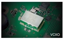
VCXO Reducing phase noise in a receiver is always a challenge as it is a natural characteristic of a receiver. The master clock of the IC-7610 utilizes a low phase noise VCXO (Voltage Controlled Crystal Oscillator), combined with Icom’s years of technical expertise to design a common power supply for the VCXO and FPGA, yielding an ultra-low phase noise. Also, a 10 MHz reference signal can be input to the IC-7610 for higher precision.
Independent Dual Receiver
Whether listening to both sides of a rare DX station running split, or looking for a multiplier on a different band or mode, the dual receivers in the IC-7610 have you covered. Two separate DIGI-SEL preselectors, two separate Band Pass Filter networks, feed two separate A/D converters into the FPGA.
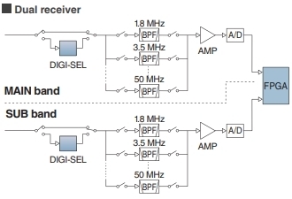
Dual receiver 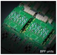
BPF units
DIGI-SEL for Main and Sub Bands
The DIGI-SEL preselectors are RF filters with sharp, narrow passband characteristics preventing Analog-to-Digital Converter overflow from large out-of-band signals when sampling the RF signals. Additionally the third and higher order IMD components are reduced. This is ideal when strong signals are received in a contest pile-up or from broadcast stations on adjacent frequencies or bands.
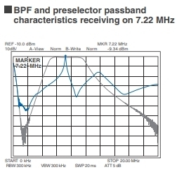
BPF and preselector passband characteristics
receiving on 7.22 MHz 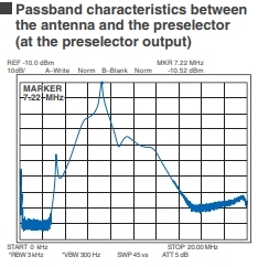
Passband characteristics between the antenna
and the preselector (at the preselector output)
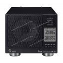
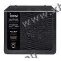
High Quality Speaker Sound
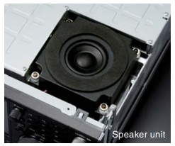
Speaker unit To finish out the receiver, is an internal speaker cabinet. The cabinet is tuned to reproduce clear, natural sounding audio, and is insulated from the radio chassis to prevent noise from vibration and panel resonance.
Digital-Up-Conversion (DUC) for Clean TX
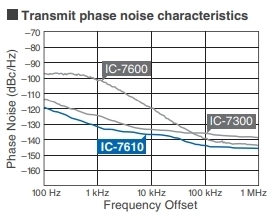
Transmit phase noise characteristics Breaking with the tradition of mixing a carrier signal with a local oscillator, a Digital-Up-Conversion (DUC) method is used to generate the required signal from the Digital-to-Analog Converter. The chart to the right shows the difference made by this new design.
Built-in Automatic Antenna Tuner
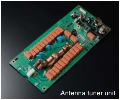
Antenna tuner unit The built-in automatic antenna tuner memorizes its settings based on your transmit frequency, so that it can recall the tuning setting when you switch operating bands. The emergency tuner function* enables you to operate for short periods of time with an antenna with a high SWR.
7-inch Color Display with Touch Screen Function
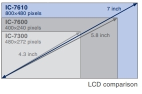
LCD comparison The large 7-inch color display shows various operating and setting information at a glance in high resolution (800 × 480 pixels.) The display clearly shows various features, for example the dual spectrum scope aligned vertically or horizontally, simulated analog meters and RTTY, PSK31/63 mode decoded messages.
Dual Receivers, Dual Spectrum Scopes
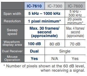
* Number of pixels shown at the 60 dB level,
when receiving a signal. The IC-7610 provides dual reception, on different bands, as does the high-speed, high-resolution spectrum scopes. Whether watching for a band opening, working a rare DX station operating split, or searching for a multiplier, the ability to watch each receiver separately allows the operator to concentrate on pulling in a weak signal. The scopes provide class-leading performance in resolution, sweep speed and a 100 dB dynamic range. To navigate around the band easier, connect a PC mouse to the USB port for point and click tuning of the receivers.
Audio Scope Flexibility
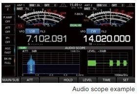
Audio scope example The Audio Scope screen shows both a FFT scope with waterfall along with an oscilloscope for both transmit and receive audio. This makes it easy to monitor AF characteristics such as microphone compressor level, filter width, notch filter, and in CW, you can monitor received CW keying wave forms.
Touch Screen and Multi-Dial Knob for Smooth Operation
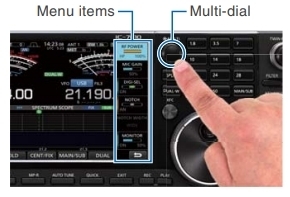 The combination of the touch screen and the multi-dial knob offers quick and smooth operation. When you push the multi-dial knob, menu items are shown on the right side of the display. You can select an item by touching the screen and can adjust the levels by turning the multi-dial knob.
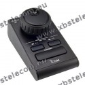
Remote Encoder for Second VFO Knob
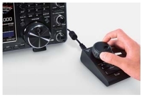 The optional RC-28 remote encoder enables you to add an external Sub dial for controlling the Sub band. Main band and Sub band can be switched with the F1 and F2 buttons and can be controlled with the RC-28. The LED above the F1 and F2 buttons turns ON to show the active band.
DVI-D Connector for an External Display Connection
The IC-7610 has a DVI-D connector for an external display. Operating frequency, setting information and spectrum scope can be observed on a large external display.
SD Card Slot and USB Port for Saving Data
When used with an SD card or USB flash drive, various contents including firmware updates, memory channels, captured screen images, and other personal settings, can be saved and loaded. TX/RX audio, voice memories, RTTY/CW memories and RTTY decode logs can be saved and used on the SD card.
I/Q Signal Output
The IC-7610 enables you to output I/Q signals from the USB connector. They can be used to analyze a spectrum range or to decode signals by a decoder software on a PC.
*This function will be provided in a future firmware update.Simplified Remote Control for RS-BA1
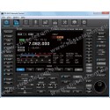
Whether from a remote part of your home QTH, or on a remote location somewhere around the world, the RS-BA1 software enables you to operate your IC-7610. Not only can you control the radio settings and have both RX/TX audio paths, you are able to display a single band spectrum scope with the waterfall. With the addition of an Ethernet connector, a base station computer is not required.
RS-BA1
Other Outstanding Features
RX antenna-
- BNC type RX IN/OUT connectors for a receiver antenna or external BPF/preamp connection
CW mode
-
- FPGA-controlled CW keying waveform shaping
- Multi-function electronic keyer
- CW pitch control from 300 Hz to 900 Hz
- Auto repeat function
- Contest serial number counter
- Normal or short Morse number style
- Double key jack system
- Full break-in and semi break-in
- CW auto tuning
- APF (Audio Peak Filter) function adjustable filter shape, width and AF level
Receiver
-
- 30 kHz to 60 MHz receiver
(Some frequencies are not guaranteed.) - Two types of preamplifiers
Preamp 1: Improves intermodulation characteristics
Preamp 2: High gain preamplifier - 3 dB – 45 dB variable attenuator
- IP+ function improves 3rd order intercept point performance
- 101 memory channels
- RTTY encoder and decoder
- Twin peak audio filter for the RTTY mode
- Adjustable AGC time constant from 0.1 to 6 seconds
- Digital twin PBT eliminates interference from adjacent signals
- Main/Sub band tracking function for diversity reception
- 30 kHz to 60 MHz receiver
Transmitter
-
- TX monitor function
- All mode power control
- VOX (Voice Operated transmission) capability
- BNC type transverter connector
- Microphone equalizer and adjustable transmit bandwidth
- 50 CTCSS tones
Operation
- Memo pad stores up to 10 operating frequencies and modes
- Quick split function
- Quick Dualwatch function
- RF gain and squelch control with a knob
- RIT and ΔTX variable up to 9.999 kHz
- UTC/local clock and timer function
- 1 Hz pitch tuning and display
- Dial lock function
- Adjustable main dial brake
- External speaker jacks for Main and Sub receivers
- Screen saver function
- Multi-function meter
(S-meter, Power, ALC, COMP, SWR, ID, VD and TEMP) - Auto tuning step function
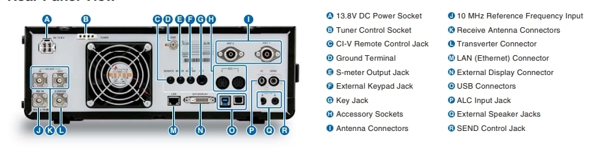
Rear Panel View
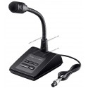
Supplied accessories (May differ depending on version)
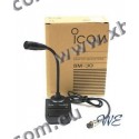
- Hand microphone, HM-219
- DC power cable
- Fuses
- Plugs
- Manuals CD / PDF version
General
| Frequency coverage: (USA version)1 |
RX: 0.030–60.00 MHz*2 TX: 1.800–1.999, 3.500–3.999, 5.255–5.405*3 7.000–7.300, 10.100–10.150, 14.000–14.350, 18.068–18.168, 21.000–21.450, 24.890–24.990, 28.000–29.700, 50.000–54.000 MHz |
|
|---|---|---|
| Frequency coverage: (EUR version)1 |
RX: 0.030–60.00 MHz*2 TX: 0.1357–0.1378, 1.810–1.999, 3.500–3.800, 7.000–7.200, 10.100–10.150, 14.000–14.350, 18.068–18.168, 21.000–21.450, 24.890–24.990, 28.000–29.700, 50.000–52.000 MHz |
|
| Mode | USB, LSB, CW, RTTY, PSK31/63, AM, FM | |
| Number of channels | 101 (99 regular, 2 scan edges) | |
| Antenna connectors | SO-239 × 2 (50Ω unbalanced (Tuner off)) BNC × 1 (RX antenna In/Out) |
|
| Power supply requirement | 13.8V DC ±15% | |
| Power consumption | Tx | 23 A (at 100 W output power) |
| Rx | 3.0 A (Standby), 3.5 A (Maximum audio) | |
| Operating temperature range | 0°C to +50°C; 32°F to 122°F | |
| Frequency stability | Less than ±0.5ppm (0°C to +50°C; 32°F to 122°F) |
|
| Frequency resolution | 1 Hz (fine) | |
| Dimensions (W×H×D) (projections not included) |
340×118×277 mm; 13.4×4.6×10.9 in |
|
| Weight (approximately) | 8.5 kg; 18.7 lb | |
*2 Guaranteed range: 0.500–29.999, 50.000–54.000 MHz.
*3 Some frequency bands are not guaranteed.
Transmitter
| Output power (HF/50 MHz) | SSB/CW/FM/RTTY/PSK: 1–100 W, AM: 1–25 W |
|
|---|---|---|
| Modulation system | SSB | Digital P.S.N. modulation |
| AM | Digital Low power modulation | |
| FM | Digital Reactance modulation | |
| Spurious emission | HF bands | Less than -50 dB |
| 50 MHz bands | Less than -63 dB | |
| Carrier suppression | More than 50 dB | |
| Unwanted sideband | More than 50 dB | |
| Microphone impedance | 600Ω | |
Receiver
| Receive system | Direct Sampling Superheterodyne | ||||
|---|---|---|---|---|---|
| Intermediate frequency | 12 kHz | ||||
| Sensitivity *4 | 0.5–1.799MHz | 1.8–29.999MHz | 28.0–29.7MHz: | 50–54MHz: | |
| SSB/CW: (at 10dB S/N) |
– | 0.16μV typ. | – | 0.13μV typ. | |
| AM: (at 10dB S/N) |
6.3μV typ. | 2.0μV typ. | – | 1.0μV typ. | |
| FM (at 12dB SINAD) |
– | – | 0.5μV typ. | 0.32μV typ. | |
| Sensitivity for RED version.*5 | 1.8–29.999MHz | 3.0–29.999MHz | 28.0–29.7MHz: | 50MHz: | |
| SSB: (at 12dB SINAD) |
10 μV emf | 0 μV emf | – | -6μV emf | |
| AM: (at 12dB SINAD) |
16 μV emf | 6 μV emf | – | 0 μV emf | |
| FM (at 12 dB SINAD) |
– | – | 0 μV emf | -6μV emf | |
| Squelch sensitivity (Threshold) |
SSB: Less than 3.2 μV (Preamp ON) FM: Less than 0.32 μV (Preamp ON) |
||||
| Selectivity (Filter shape: Sharp) | More than | Less than | |||
| SSB (BW: 2.4kHz, sharp) |
2.4 kHz/–6 dB | 3.6 kHz/–60 dB | |||
| CW (BW: 500Hz, sharp) |
500 Hz/–6 dB | 700 Hz/–60 dB | |||
| RTTY (BW: 500Hz, sharp) |
500 Hz/–6 dB | 700 Hz/–60 dB | |||
| AM (BW: 6kHz) |
6.0 kHz/–6 dB | 15 kHz/–60 dB | |||
| FM (BW: 15kHz) |
12.0 kHz/–6 dB | 20 kHz/–60 dB | |||
| Spurious and image rejection | HF bands | More than 70dB | |||
| 50 MHz band | More than 70 dB (Except for ADC Aliasing) | ||||
| Audio output power (at 13.8V DC) |
More than 2.0 W (at 10% distortion with an 8Ω load) |
||||
*5 Less than, HF: Preamp 1 ON, filter shape Soft, 50 MHz: Preamp 2 ON, filter shape Soft, BW: SSB=2.4 kHz, AM=4 kHz, 60% modulation, FM=7 kHz, 60% modulation
Tuner
| Frequency range | 1.9–50 MHz bands |
|---|---|
| Matching impedance range | 16.7Ω –150Ω unbalanced (VSWR better than 3: 1) |
| Tuning accuracy | VSWR 1.5: 1 or less |
| Tuning time | 2–3 seconds (average) (Maximum 15 seconds) |
All stated specifications are subject to change without notice or obligation.
Reviews
No customer reviews for the moment.